
Long Time Between Drinks
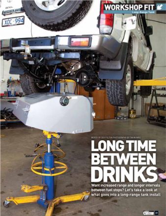
It’s a generally accepted fact that the only way to significantly increase your fuel range is to fit a long range fuel tank.
Yes, you can tweak your engine, and adjust your driving style to maximise your engine’s efficiency. However if you really want to travel further before stopping for fuel then a larger tank should be on your shopping list.
As an added bonus, they are often much better engineered and stronger than your standard tank and negate the need to carry bulky jerry cans which, unless they are able to be vented out of the cab, must be carried on the exterior of your vehicle which can mean a lot of weight right where you don’t want it.
While installation of a replacement fuel tank is certainly achievable by the average home mechanic, access to a hoist and other specialist equipment make it infinitely easier. A workshop will be able to do it quickly, neatly, and relatively inexpensively when you weigh up the time spent driving instead of lying under your truck.
We ducked down to Long Range Automotive in Lilydale and got the guys to show us how they go about building one of their replacement tanks for a diesel Toyota Troopy, and what exactly goes into an installation.
the how to for an lra tank
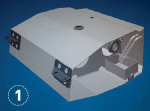
Step 1. LRA designs all its tanks in-house using AutoCAD Inventor, which is a common industry CAD program. The cutaway shows the internal baffles. They have also incorporated a chamber to cater for fuel expansion. All tanks are pressure-tested twice before fitting to make sure no annoying pinhole leaks show themselves on your first fill up.
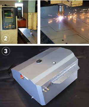
Step 2. The shapes of the separate tank pieces are then transferred on to a sheet of 2mm T125CQ (Commercial Quality) aluminised steel. This means that the steel that has been hot dipped in a silicon and aluminium alloy which makes it very resistant to rust yet maintains the qualities of hard-wearing steel at anything up to 800°C. So it’s perfect for fuel tanks. The sheet is then cut out using the in house high-tech Farley computer-controlled (CNC) high-definition plasma profile cutter. This basically ensures that each piece fits together perfectly upon assembly and allows maximum weld penetration between the panels.
Step 3. The tank is then welded up using the trusty MIG and is etch primed and finished in a durable hammertone enamel to prevent rust rearing its ugly head. While it’s waiting to be installed, all outlets and inlets on the tank are temporarily plugged or have brass barbs fitted to ensure the tank remains clean and dust free. Check out the heavy-duty mounting brackets that are both stitch and rosette (plug) welded.
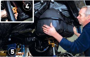
Step 4. The first step of the installation process is to start removing the OE tank in preparation for its replacement. Careful attention must be used here. All electrics and fuel/breather lines are disconnected, with clamps being used on both the main fuel line as well as the return line to prevent diesel going everywhere. While most of us are content to use vice grips, the guys from LRA use purpose built clamps. A sign of their professional approach.
Step 5. Once all lines have been removed from the OE tank and secured out of the way, a transmission jack is used to brace the tank in position while all the bolts are undone. When the bolts are all out, the tank is lowered out from between the chassis rails using the jack. Makes you appreciate workshops eh? Imagine trying to do this on your back in the driveway while undoing bolts with your teeth and supporting that tank with your knees as you’re being showered in diesel! Thanks but no thanks.
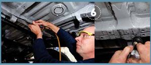
Step 6. On this particular install, a couple of the OE brackets would have fouled on the replacement tank, so the air hacksaw is called into action. Again, the devil is in the detail and the lads didn’t disappoint. Once Anthony had the bracket cut off, the bare metal was deburred using the die grinder and painted over to prevent rust from occurring. The completion of these little jobs is the sign of a competent workshop.
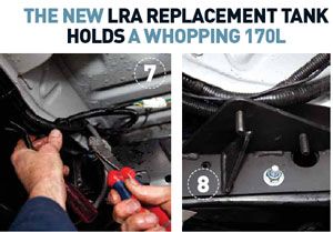
Step 7. The wiring is left as stock standard as possible with little to no change to the factory loom or connectors. Leaving things like this unchanged greatly reduces the chance of things going wrong down the line. Like the old adage says, if it ain’t broke…
Step 8. Where possible, the mounting brackets for the new tank utilise existing bolt holes on the vehicle. However, this is not always possible. In order to mount the tank in the appropriate position, a couple of new holes had to be drilled. You can see the hole through the chassis in the upper left mounting hole, while the lower hole has already been filled with a high-tensile bolt and nyloc nut. At this stage it’s always worth double-checking the mounts and tank still line up. There’s nothing worse than redoing work when it could have been.
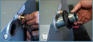
Step 9. All the brass threaded fittings are wrapped with thread tape and bolted into the pre-tapped holes in the tank. A thread locking compound is used liberally to make sure that there is no chance of the fittings shaking loose regardless of how many bone-jarring corrugations the tank will be subjected to.
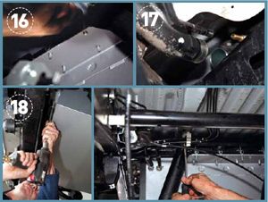
Step 10. The filler from the OE tank is unbolted and removed. Re-using factory components where possible cuts down on costs and saves having to customise components to fit. The LRA tanks are designed to accept the OE filler, so there are no dramas with attachment points lining up.
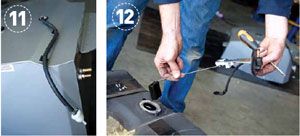
Step 11. A new breather line is attached and then run off the top of the tank. It’s much easier to do this step now rather than try and get your paws over the top of the tank later. Note the clips used to keep the line neatly in place and prevent it from catching or fouling on any other under-body components.
Step 12. In order for the standard dash gauge to read the correct fuel level of the new tank, the factory float and associated electrics are retained. The problem with this is that the LRA replacement is significantly ‘deeper’ than the OE tank. When using a float, this means that the gauge will read empty way before it actually is. Obviously, this is not ideal as you would have no way of knowing when you were actually low on fuel.
Step 13. The solution is to lengthen the float rod so that it sits lower in the tank and provides an accurate reading. It’s a fairly simple process. The float assembly is cut in two and a pre-determined 50mm length of rod is welded in to place to extend it.
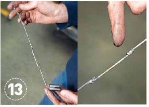
Step 14. And here you can see it in action, both simulated at empty, and then again at full. The float gauge is then reattached to the tank and the associated wiring routed, so as to be easily reconnected in preparation for fitting the tank between the frame rails.
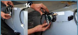
Step 15. Anthony carefully jacks the new tank in to position under the truck. Care is taken to make sure everything lines up nicely and nothing is out of place. In this case, the shackle bolts had to be flipped around so as not to contact the filler neck while it was being installed. This also allows the leaf springs to be removed without removing the tank if the owner decides to upgrade the suspension at a later date. No big deal, but it’s another example of the attention to detail that’s needed to complete a job like this properly.
Step 16. Perfect fit. Geez, you’d think these guys had done this before or something! With the tank sitting nicely between the rails, the high-tensile bolts and nyloc nuts are all attached and done up finger tight to make sure the tank is not going to move around while the plumbing is being fitted up.
Step 17. Here we can see the breather outlet and filler neck lined up perfectly with the OE components on the truck. This actually fits a little closer than the factory tank, so the rubber connecting hoses were measured and trimmed to size before being attached with new stainless hose clamps.
Step 18. Once all the hoses and electrics have been hooked up, the mounting bolts are tightened up and everything is given the once-over to make sure that the tank is firmly in place and all hoses and lines are where they should be.

Step 19. Finally the fuel delivery and return lines are attached, via rated rubber hose, to the hard lines and clipped in to place to minimise vibration. Note the four U-bolts that attach the tank securely to the rear crossmember.
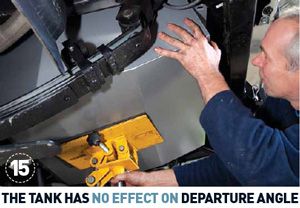
Step 20. And there you have it. The tank has no effect on departure angle and sits neatly under the truck. The tank is designed to slide over any obstacles and is largely protected by the rear tow-bar. The factory tank held 90L of diesel, whereas the new LRA replacement tank holds a whopping 170L. This is nearly a 90% increase in fuel capacity and a massive increase in the distance able to be covered between visits to the servo, which means the vehicle is capable of staying off the black top for a lot longer.
What's New

Long Range Automotive
23 Industry Court, Lilydale VIC 3140 Australia
PH: +61 3 9739 5667
